
Oil and Gas Reservoir Storage
Oil and gas reservoir sequestration is the storage of carbon dioxide (CO2) in mature and/or partially depleted oil and gas reservoirs, which have held crude oil or gas reserves, and thus have geologic conditions suitable for CO2 storage (The Energy Lab, 2009). A typical reservoir consists of a layer of permeable rock with another layer of impermeable rock above, forming a trap that can hold CO2 inside in the same way it keeps oil and gas (Plasynsky, 2008). Additionally, injecting CO2 into oil and gas reservoirs can be used to increase the amount of oil and natural gas extracted from the earth in two processes known as CO2-enhanced oil recovery and CO2-enhanced gas recovery.
CO2-enhanced oil recovery is a method used to extract oil from the earth by injecting carbon dioxide (CO2 ) into oil reservoirs (Kuuskraa et al, 2008). Once injected, CO2 reacts chemically and physically with the rocks of the reservoir and the oil within, optimizing oil recovery by (a) reducing capillary forces, which inhibit oil flow through the pores of the reservoir; (b) increasing the volume of the oil (oil swelling) and, thus, reducing the oil's viscosity; (c) forming favorable complex phase changes in the oil that increase its fluidity; and (d) maintaining favorable mobility characteristics for oil and CO2 to improve the volume sweep (replacement) efficiency (The Energy Lab, 2009; Tzimas et al, 2005).
There are two methods of enhanced oil recovery: miscible displacement and immiscible displacement. In the miscible displacement process, the injected CO2 dissolves in the oil under the appropriate conditions, thus increasing the oil flow rate for the reasons mentioned above. To maintain a stable flow, the Water Alternating Gas technique is commonly used in miscible CO2-enhanced oil recovery. In the Water Alternating Gas injection method, water is injected with the CO2 or in alternation with the CO2 to displace the oil towards the production well (Nezhad et al, 2006; Tzimas et al, 2005) (see figure 1). Immiscible displacement occurs when the reservoir has lower pressure. In this process process in which some of the injected CO2 still dissolves in the oil, while the rest is used as an artificial air cap, pushing oil simultaneously downwards and towards the rim of the reservoir where the producing wells are located. This injection method is called Gravity Stable Gas Injection (Tzimas et al, 2005) (see figure 2). When oil containing CO2 is extracted, the CO2 is separated from the oil and reused for the oil recovery until the capacity of CO2 storage is reached. The field will then be sealed with the CO2 trapped inside (Kuuskraa et al, 2008; Aycaguer, 2001).
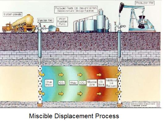
figure 1 above
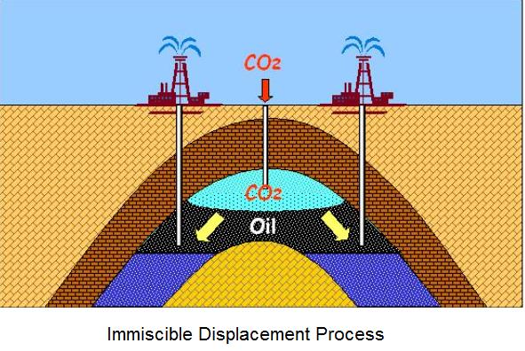
figure 2 above
(Plasynsky, 2008; Tzimas et al, 2009)
According to a theoretical model created by Andrew Leach et al, the optimal fraction of oil extraction and CO2 sequestration is likely to decline over time and will eventuall reach zero at a certain termination time. Based on numerical simulations in Wyoming, the optimal injection rate of CO2 is 54.47 Mt/yr and the termination time is approximately 22 years (Leach et al, 2009).
CO2-enhanced gas recovery is a method used to recover depleted natural gas by injecting CO2 in natural gas reservoirs in a manner similar to CO2-enhanced oil recovery. Although CO2-enhanced gas recovery has not yet been commercially tested and is not as profitable as CO2-enhanced oil recovery, its potential for CO2 sequestration is promising. Recovery of natural gas is highly efficient, leaving a large amount of void space to store CO2 (Stevens et al, 2001).
Advantages:
- The CO2 is trapped in the reservoirs in the same way oil and gas are stored. Therefore, this method can bypass two important barriers of geological storage: establishing mineral rights and long-term liability of the injected CO2 (Kuuskraa et al, 2008).
- After taking account of the carbon content of the incremental oil produced, approximately 70% of the CO2 injected is stored. A barrel of oil obtained using enhanced oil recovery releases 0.42 tonnes of CO2 into the atmosphere whereas 0.52 to 0.64 tonnes are injected into the reservoir (Biello, 2009).
- 39 to 48 billion barrels of oil can be recovered, supporting the economy and creating incentives for oil companies (Kuuskraa et al, 2008).
- A CO2 market will be created that can balance out the cost of carbon capture, transportation, and storage. The size of this market is about 7,500 tonnes between now and 2030 (Kuuskraa et al, 2008).
- Oil and gas fields are generally well understood due to previous work done by oil and gas companies.
Disadvantages:
- To reduce spending on CO2, companies may pump the CO2 out of the storage sites to use in other fields, rather than letting it remain sequestered.
- CO2 is likely to react with the high-bitumen content in raw oil, thereby causing the bitumen to set, decreasing the porosity of the oil bed (Zhu et al, 2001)
- Injected CO2 may cause mineral dissolution of carbonic acid at the injection site, causing a significant difference in mineral make-up before and after injection and disrupting the ecosystem (Nightingale et al, 2009)
- When compared to saline aquifers, the capacity of oil reservoirs are low.
Potential Storage Sites:
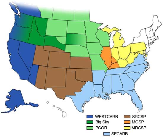
CO2 Storage Resource Estimates by Regional Carbon Sequestration Partnership for Oil and Gas Reservoirs
CO2 Storage Resource Estimates by Regional Carbon Sequestration Partnership for Oil and Gas Reservoirs
|
Regional Carbon Sequestration Partnership |
Billion Tonnes |
|
|
Big Sky regional Carbon sequestration Partnership (BSCSP) |
1.5 |
|
|
Midwest Geological Sequestration Consortium (MGSC) |
0.4 |
|
|
Midwest Regional Carbon Sequestration Partnership (MRCSP) |
8.4 |
|
|
Plains CO2 Reduction Partnership (PCOR) |
24.1 |
|
|
Southeast Regional Carbon Sequestration Partnership (SECARB) |
31.1 |
|
|
Southwest Regional Partnership on Carbon Sequestration (SWP) |
65.0 |
|
|
West Coast Regional Carbon Sequestration Partnership (WESTCARB) |
7.7 |
|
|
TOTAL |
138 |
|
(Carbon Sequestration Atlas of the United States and Canada, 2008)
There are about 2,100 reservoirs in the Lower 48 states that meet the criteria below for CO2-enhanced oil recovery miscible flooding: (Mohan, n.d.)
i. API gravity > 22°
ii. reservoir pressure greater than the minimum miscibility pressure
iii. depth > 2,500 ft
iv. oil viscosity < 10 cP
v. current oil saturation >20% of pore volume
vi. sandstone or carbonate rock
Capacity Estimates:
- Total potential in oil and gas reservoirs: 870 - 1040 Gt
- Potential CO2 sequestered by CO2-enhanced oil recovery: 120 - 140 Gt (Plasynsky, 2008; Stevens et al, 2001)
- Potential CO2 sequestered by CO2-enhanced gas recovery: 750 - 900 Gt (Stevens et al, 2001; Depleted oil & gas fields for CO2 storage, n.d.)
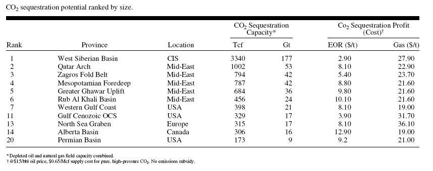
CO2 sequestration potential of twenty oil and gas reservoirs, ranked by size (Stevens et al, 2001)
Cost Estimates: (for a company) (Plasynsky, 2008)
- Capital costs - $0.8/Bbl
- Operations and maintenance - $2.70/Bbl
- CO2 purchase: 5Mcf/Bbl at $0.65/Mcf
Shell concludes that a conventional carbon dioxide enhanced oil recovery project would be economically feasible at $18 per barrel of oil.
Assuming that the amount of CO2 needed could be delivered to the oil and gas field with no cost, global CO2 sequestration capacity and sequestration costs would be as presented below.
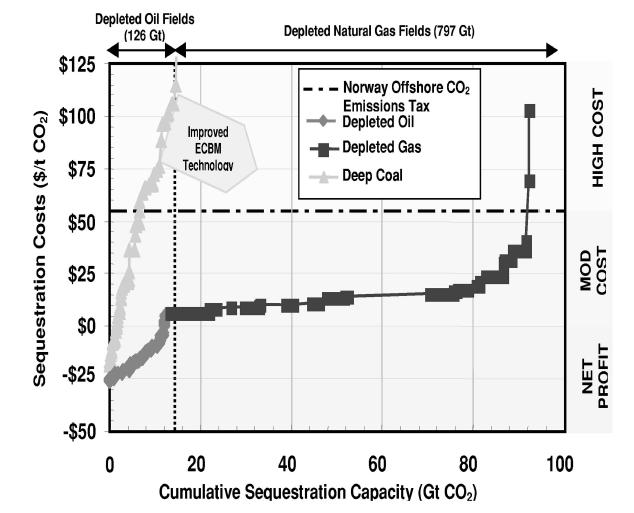
(Stevens et al. 2001)
Based on the information provided by Stevens et al and Plasynski, assuming that CO2 is delivered to sites with no cost and that the profit made by oil production is not taken into account, it is calulated that the cost of sequestering 1 Gt CO2 is approximately $12 million.
Readiness:
The Scurry Area Canyon Reef Operators Committee oil field has pumped in 140 Mt of super-critical CO2 since 1972. The result is that 80 Mt of CO2 have stayed trapped in the reservoir (Biello, 2009).
The Great Plains Synfuel Plant in North Dakota has pumped nearly two million metric tonnes of CO2 per year to the Weyburn oil field in Saskatchewan since 2000. The U.S. has at least 100 CO2- enhanced oil recovery sites and 5,000 km of CO2 pipelines (Biello, 2009).